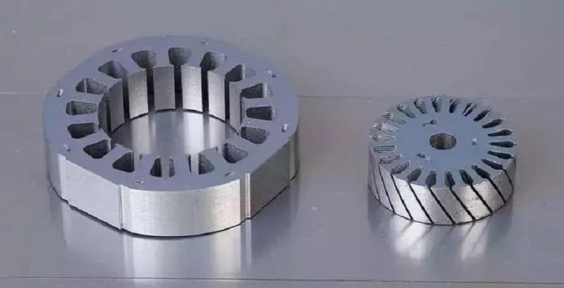
In the motor industry, the stator and rotor cores are one of the important parts of the motor, and its quality directly affects the technical performance of the motor. The traditional method of making the iron core is to punch out the fixed and rotor punching pieces (loose pieces) with ordinary molds, and then make the iron core by rivet riveting, clipping or argon arc welding and other processes. For the AC motor rotor The iron core needs to be twisted out of the chute by hand. The stepper motor requires uniform magnetic properties and thickness directions of the stator and rotor cores. The stator core and rotor core punches are required to rotate at a certain angle, such as using the traditional method. Production, low efficiency, precision is difficult to meet the technical requirements. Now with the rapid development of high-speed stamping technology, in the fields of motors and electrical appliances, high-speed stamping multi-station progressive dies have been widely used to manufacture automatic laminated structural iron cores, in which the stator and rotor cores can also be twisted and stacked. There is a large-angle rotary stacking riveting structure between the groove and the punching plate. Compared with the ordinary punching die, the multi-station progressive die has high punching precision, high production efficiency, long service life, and consistent dimensional accuracy of the punched iron core. Good, easy to realize automation, suitable for mass production and other advantages, it is the direction of the development of precision molds in the motor industry.
Stator and rotor automatic stacking riveting progressive die has high manufacturing precision, advanced structure, with high technical requirements of the rotary mechanism, counting separation mechanism and safety mechanism, etc., automatic stacking riveting of iron core, rotor with skewed stacking riveting, large-angle rotation The stamping steps of stacked riveting are completed on the blanking station of stator and rotor. The main parts of the progressive die, the punch and the die, are made of hard alloy materials. Each cutting edge can be punched more than 1.5 million times, and the total life of the die is more than 120 million times.
Motor stator and rotor core automatic riveting technology
The automatic stacking riveting technology on the progressive die is to complete the traditional process of making iron cores (punching out of loose pieces-alignment-riveting) in a pair of molds, that is, on the basis of progressive dies, it adds The new stamping process technology, in addition to punching sheet shape requirements such as shaft holes and slot holes on the stator and rotor, has added the stacking points required for the stacking riveting of the stator and rotor cores and the counting holes for the separation of the stacking points. Stamping station, and change the blanking station of the original stator and rotor to the blanking station first, and then make each punching sheet form a stacking riveting process and a lamination counting and separation process (to ensure the thickness of the iron core). , if the stator and rotor cores need to have the function of torsion and rotation stack riveting, the lower mold of the progressive die rotor or stator blanking station should have a twist mechanism or a rotation mechanism, and the stack riveting point is constantly changed on the punching sheet This function can be realized by turning the position or turning the position, so as to meet the technical requirements of automatically completing the stacking riveting and rotary stacking riveting of punching sheets in a pair of molds.
The process of automatic lamination formation of iron core
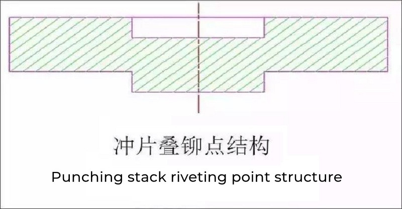
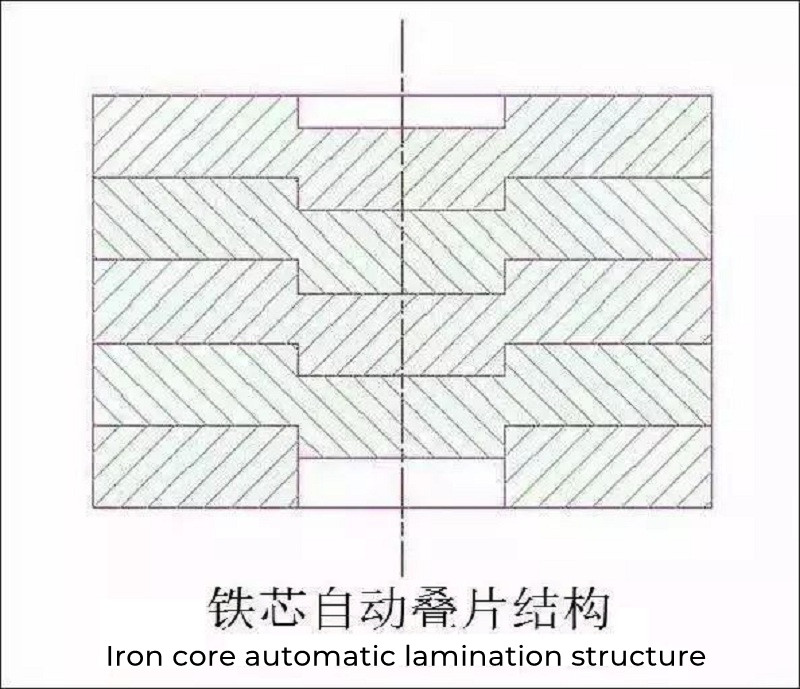
Punch out certain geometrical overlapping riveting points on the appropriate parts of the stator and rotor punching sheets. The form of the overlapping riveting points is shown in Figure 2. The upper part is a concave hole and the lower part is convex. Then, the upper part of the same nominal size When the convex part of the punching sheet is embedded into the concave hole of the next punching sheet, an "interference" is naturally formed in the tightening ring of the blanking die in the mold to achieve the purpose of fastening the connection, as shown in Figure 3. The process of forming the iron core in the mold is to make the convex part of the stacking point of the upper piece correctly overlap with the concave hole of the stacking point of the lower piece at the punching and blanking station. When the pressure of the material punch acts, the reaction force generated by the friction between the shape and the die wall of the lower piece makes the two pieces overlap.
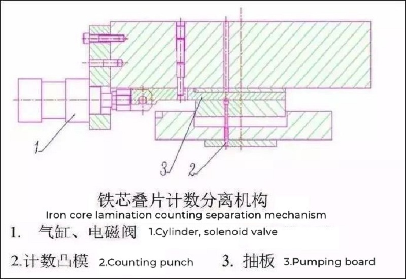
The control method for the thickness of the core laminations is to punch through the riveting points on the last punched sheet when the number of iron cores is predetermined, so that the iron core is separated according to the predetermined number of pieces. An automatic lamination counting and separating device is provided on the mold structure.
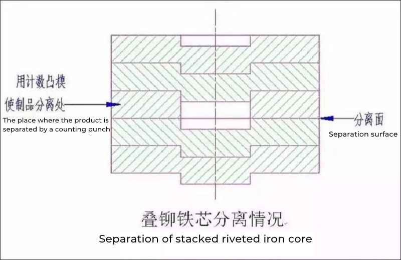
There is a pumping plate mechanism on the counting punch, the pumping plate is driven by the cylinder, the action of the cylinder is controlled by the solenoid valve, and the solenoid valve moves according to the instructions issued by the control box. Each stroke signal of the punching machine is input into the control box. When the set number of pieces is punched, the control box will send out a signal to make the pumping plate move through the solenoid valve and the cylinder, so that the counting punch can achieve the purpose of counting and separation. That is to say, the purpose of punching through the metering hole and not punching the metering hole is achieved at the riveting point of the punching sheet. The lamination thickness of the iron core can be set by yourself. In addition, due to the needs of the supporting structure, the shaft holes of some rotor cores are required to be punched with 2 or 3 shoulder counterbores.
Main reasons affecting the quality of magnesium oxide coating solution
There are two types of core stack riveting structure: the first one is dense stacking type, that is, the iron core stacked into a group does not need to be repressed outside the mold, and the bonding force of the core stack riveting can be achieved after the mold is released. . The second type is the semi-dense stacking type. There are gaps between the stacked and riveted iron core punches when the mold is released, and further pressure is required to ensure the bonding force.
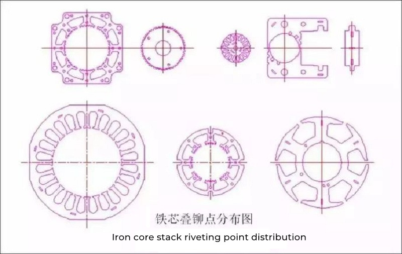
The setting and quantity determination of core stacking riveting: the selection of the position of core stacking riveting points should be determined according to the geometric shape of the punching sheet, and at the same time, taking into account the electromagnetic performance and use requirements of the motor, the position of the stacking riveting points should be considered on the mold. Whether there is interference in the positions of the punch and die inserts and the strength of the distance between the position of the corresponding stacked riveting ejector pin hole of the blanking punch and the edge. The distribution of stacked riveting points on the iron core should be symmetrical and uniform. The number and size of stacked riveting points should be determined according to the required bonding force between the iron core punches, and the manufacturing process of the mold must be taken into account. For example, if there is a large-angle rotary stacking riveting between the iron core punching pieces, the equal division requirements of the stacking riveting point should also be considered.
Structural Features of Modern Die for Motor Stator and Rotor Core
1. The mold adopts a double-guiding structure, that is, the upper and lower mold bases are guided by more than four large ball-type guide pillars, and each unloading device and the upper and lower mold bases are guided by four small guide pillars to ensure reliable guide accuracy of the mold;
2. From the technical considerations of convenient manufacturing, testing, maintenance, and assembly, the mold sheet adopts more block-type structures and combined structures;
3. In addition to the common structures of progressive die such as step guide system, unloading system (composed of unloading plate main body and split unloading plate), material guiding system and safety system (misfeed detection device), there are The special structure of the progressive die of the motor iron core: such as the counting and separating device of the automatic lamination of the iron core (that is, the pumping plate structure device), the stacking riveting point structure of the punched iron core and the ejector rod structure of the iron core blanking stacking riveting point, punching sheet Blanking and re-stacking riveting tightening structure, twisting or turning device, safety device for large turning, etc.;
4. Since the main parts of the progressive die, the punch and the die are usually made of hard alloy, considering the processing characteristics and the price of the material, the punch adopts a fixed structure of a pressing plate, and the die adopts an inlaid structure, which is easy to assemble and replace.
What should we pay attention to when selecting stainless steel colored sheets
2021-10-265 Benefits Of Stainless Steel Tanker
2023-02-27Three main links of pickling stainless steel pipe processing
2021-02-19Control Technologies and Material Optimization for Eddy Current Losses in Iron Cores
2025-02-22Properties and applications of electrical steel stainless steel tubes
2023-11-25Causes of Corrosion of Stainless Steel Metro Body
2022-11-22